Fault finding
Startup process
The addon follows the following startup process:
Load config, sensor definitions and schedules
The logs will show if you use any unknown or deprecated sensors, if you have anything wrong in your custom sensors, and the intended schedule for reading sensors.
Connect to the Inverter
Connect and read the Inverter details (i.e. serial number). This is the first step to ensure the connection is working.
If this read fails, you need to follow the fault finding guide below. It could be a cabling issue, a configuration issue, or a hardware issue.
If successful, the only check is that you have the correct serial number in your config. The log will show:
txtINFO ############################################################ INFO Inverter serial number '*1234' INFO ############################################################If the device settings was read successfully, it will read all configured sensors to ensure you have some values at startup
Connect to the MQTT server
Publish the discovery data for Home Assistant, and also remove discovery data if required
If this step fails, you will not see any entities in Home Assistant and you need to check your MQTT server settings.
Once the startup is complete, the addon will continue to read & publish sensor data. During this process you will occasionally see read failures. As long as this does not happen on every read, you can probably continue using the addon, but can consider reducing sensors, relaxing the read schedules, etc.
If you poll several inverters on one RS485 bus and one unit stops replying, it might enter a stale state so the bus is not blocked. On the dev/edge add-on you can tune STALE_INVERTER_AFTER_SECONDS
STALE_INVERTER_SKIP_SECONDS
(see Multi add-on options). After each successful Modbus read, a timer is armed: if reads are still failing once that many seconds have passed since the last success, the add-on pauses normal polling for that inverter for the configured skip period, then probes the serial register once before resuming or extending stale quiet.
If you fail to get a reply from the inverter, typically if step #2 fails, please check the following:
(A) Cabling & connection
While fault finding use as short as possible cable, outside any sprague/trunking. Once everything works, you can switch to a more permanent, much longer cable.
If you cannot establish a connection, check the RS485 adaptor and cabling. Are you plugged into the correct port, is your connector crimped correctly?
TIP
Many newer Sunsynk/Deye hybrids use one BMS RJ45 socket for both RS485 (what this add-on uses) and CAN (battery management). If the battery already uses that port, you cannot simply “share” a normal patch cable—you need a splitter or Y-cable that keeps CAN on its pair and RS485 on pins 1–3 only on the adaptor leg. Pinout, splitter layouts, and what goes wrong if all eight wires are duplicated to both sides are covered in Adaptors & Wiring (continue through If the battery already uses this port and Pin reference).
Other factors that might impact connection, or reliability:
- Use a RJ45 converter with a GROUND pin. Ensure the ground is connected.
- Re-crimp your RJ45 connector.
- Use a good quality solid CAT5e/CAT6 cable.
- Ensure the data line is using a twisted pair.
- Ensure your RS485 cable does not run parallel to other electrical cables (AC or DC), to reduce interference. e.g. in trunking.
- If interference is a problem, are you using a twisted pair in the cable?
- If interference is a problem, it could also help to use a shielded cable. Ground the shield at ONE end only (i.e. on the USB adaptor side and then just use normal plastic RJ45 connector on the inverter side.)
- If you still fail to make a connection, test the line voltage resistor (see Reducing timeouts below)
(B) Configuration
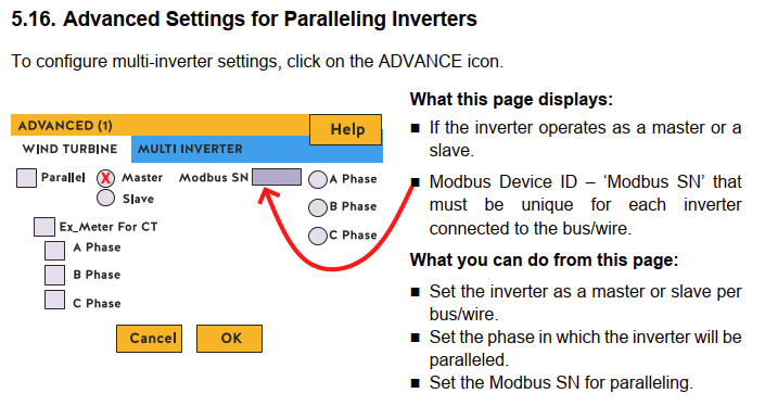
Check the Modbus Server ID
Ensure the Modbus Server ID (MODBUS_ID config setting) matches the configured Modbus SN value of the inverter. This value must not be zero.
View/update the Modbus server ID on your inverter under "Advanced Settings" / "Multi-Inverter".
Please note that this can be reset to zero after a software upgrade on your inverter, and this will stop the addon from reading data from your inverter. Resetting it to the previous value (the value the value in MODBUS_ID if you had this working previously), and then restarting the inverter should fix the issue.
Only a single connection to the serial port
Ensure you only have a single addon connected to the serial port. The following can all potentially access the USB port: mbusd, Node RED, the normal and dev addon version.
If you need to have multiple connections to the serial port: ONLY connect mbusd to the serial port. Connect all addons to mbusd (e.g. tcp://192.168.1.x:503).
(C) Reducing timeouts
If you get many timeouts, or if the addon does not read all your sensors on startup (i.e. you see Retrying individual sensors in the log), you can try the following:
- Set
READ_SENSORS_BATCH_SIZEto a smaller value, i.e. 8. - The most reliable way to connect is to use mbusd to the serial port & connect the addon to mbusd at
tcp://<ip>:502. The mbusd instance/addon can be on the same physical device or a remote device.
Check the cabling and connection again. Use a 1m cable and stand next to the inverter while testing.
Direct serial
If your RS485 adaptor is plugged directly into your host, connecting directly to the serial port PORT: "/usb/ttyX" might not give you the best results.
Once you have a working connection (reading the serial), consider introducing mbusd into your setup, in this configuration mbus connects to the serial port and the addon connects via TCP, typically: PORT: tcp://homeassistant.local:502
mbusd and the pymodbus driver gives the best results on stable multi. On dev-edge, the modbusrs driver can connect directly to a serial port without mbusd; see configuration.
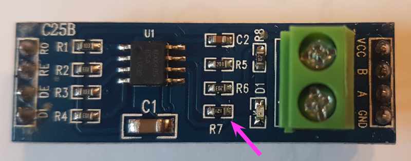
Check line voltage / termination resistor
If your RS485 adapter has a termination resistor (typically 120 ohms), try removing it.
To check, disconnect the adapter and use a multimeter to measure the resistance between A & B.
The d.c. voltage between A/B on the sunsynk RS485 connection should idle around 4-5v with nothing connected, but this may drop to around 0.5v with the 120 ohm load.
RS485 devices are typically multi-drop with a termination resistor on the first and last devices. However, the RS485 BMS port may only be intended to connect to a single device.