
Adaptors & Wiring
RS485 wiring
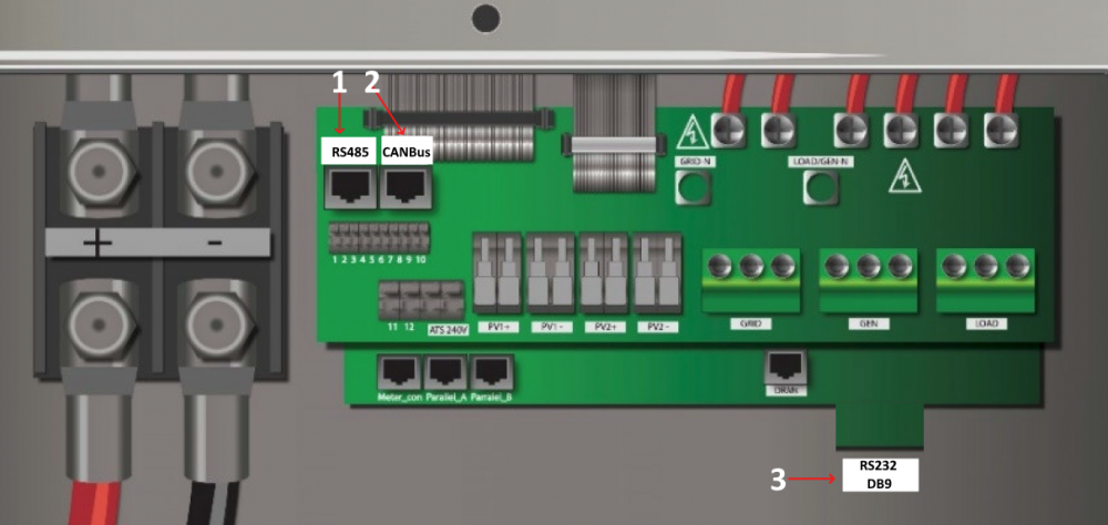
Dedicated port
RS485 requires a twisted pair, this works with CAT5 network cable and RJ-45 connectors.
If the RJ-45 connector on the inverter side is crimped according to T568A/T568B, you can use the pinout in the following table. If the two outermost colors you see on the connector are brown and green, it is probably T568A; if they are brown and orange, it is probably T568B.
| RJ45 Pin (inverter side) | Wire Color (T568A) | Wire Color (T568B) | RS485 pins |
|---|---|---|---|
| 1 | Green-White | Orange-White | B/D- |
| 2 | Green | Orange | A/D+ |
| 3 | Orange-White | Green-White | GND |
Combined RS485/CAN port ("2-in-1" BMS port)
On many newer Sunsynk and Deye hybrid inverters, the BMS RJ45 socket is a single physical connector that carries two independent buses:
- Pins 1–3 — Modbus RTU over RS485 (same mapping as the table above). This is what the add-on uses when you wire an RS485 adaptor or Ethernet gateway to that port.
- Pins 4–5 — CAN high and low between the inverter and a compatible lithium battery BMS.
Because RS485 and CAN use different pairs, the inverter can talk to the battery on CAN while you attach a monitor on RS485 if both branches are wired correctly.
If the battery already uses this port
You cannot simply unplug the battery cable and leave the battery unmanaged. You need either:
- A passive RJ45 splitter (one plug into the inverter, two sockets): one lead to the battery with only the pins the battery needs (usually CAN on 4–5, plus GND if required by that cable), and one lead to your RS485 device with only pins 1–3 (and no accidental connection of RS485 into the battery end), or
- A custom Y cable built to the same rule: inverter → battery path preserves CAN; inverter → adaptor path is only the RS485 pair and reference ground.
Why that matters
If a homemade splitter or patch cable feeds all eight pins to both the battery and an RS485 adaptor, RS485 signals can appear on pins at the battery that were not designed for them, which can disrupt BMS communication or monitoring. The battery leg should not carry RS485 A/B unless the battery documentation explicitly says so.
Pin reference (inverter RJ45, typical 2-in-1 BMS port)
| RJ45 pin | Wire Color (T568A) | Wire Color (T568B) | Typical signal | Notes |
|---|---|---|---|---|
| 1 | Green-White | Orange-White | RS485 B (D−) | Same as the dedicated port |
| 2 | Green | Orange | RS485 A (D+) | Same as the dedicated port |
| 3 | Orange-White | Green-White | GND | Same as the dedicated port |
| 4 | Blue | Blue | CAN high | Battery BMS |
| 5 | Blue-White | Blue-White | CAN low | Battery BMS |
| 6 | Orange | Green | Often unused | |
| 7 | Brown-White | Brown-White | Often unused | |
| 8 | Brown | Brown | Often unused |
Exact pin use can vary by model and firmware; always check the BMS / communications section of your inverter manual before building or buying a splitter.
DB9 / dongle port
Many Sunsynk/Deye inverters expose a DB9 connector for the Sunsynk/Solarman WiFi data logger. This port runs Modbus RTU at RS‑232 levels (TX/RX vs signal ground).
The port can also supply DC power for the dongle (typically +12 Vdc on pin 9 with GND on pin 5 — always confirm in your model’s manual).
| DB9 Pin | Inverter signal | Connect to (USB‑RS‑232) |
|---|---|---|
| 2 | TX | Adaptor RX |
| 3 | RX | Adaptor TX |
| 5 | D‑GND | GND |
| 9 | Vdc | Typically 12v |
WARNING
- The data lines are RS‑232 (single‑ended TX/RX), not RS‑485. Use a USB‑RS‑232 (or equivalent) adaptor: inverter TX (2) → adaptor RX, RX (3) → adaptor TX, GND (5) → adaptor GND.
- Pin 9 is power, not a signal ground. Measure voltage and polarity before reusing a custom cable — Solarman LSW‑3 style loggers are often specified for DC 5–12 V from the inverter.
USB-to-RS485 adaptors
Waveshare USB-to-RS485 example
This is my preferred adaptor. It includes a GND and lightning/ESD protection, TVS diodes and a resettable fuse.
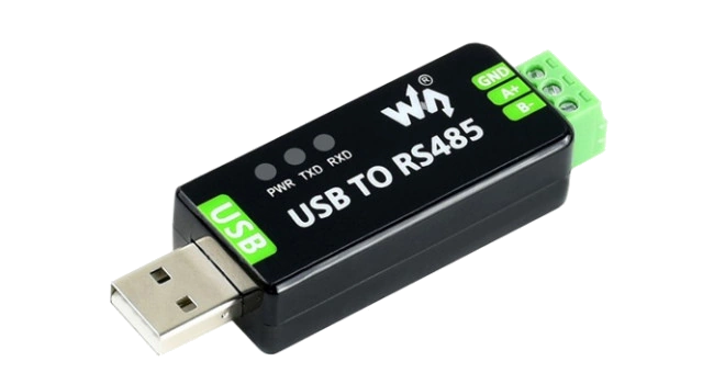
Waveshare also has a RS485-to-Ethernet module.
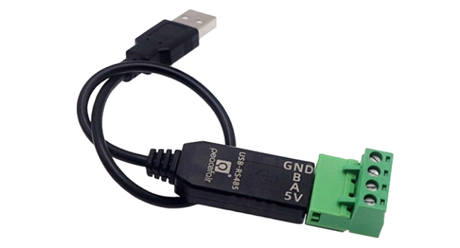
USB-to-RS485 adaptor with cable example
Includes a GND and TVS diode and USB self recovery options.
Other tested adaptors
USB-to-RS485 3 Pin adaptor example
Includes a GND and TVS diode and USB self recovery options.
2-Wire USB-to-RS485 example
This is the adaptor I started with. It works, but does not include a GND, so your success might vary.

Ethernet-to-RS485 gateways
Waveshare RS232/485/422 TO POE ETH (B)
Waveshare shop | Waveshare wiki
This device can connect via RS485 or directly to the DB9 (RS232) port.
It comes in a PoE variant and has electrical iolation on all ports.
USR-W630 Wifi-to-RS485
This is a tested Wifi-to-RS485 gateway, which also includes a GND.
Requires
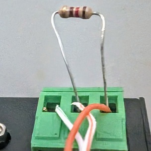
READ_SENSORS_BATCH_SIZEset to 8 or lessA 120 Ohm (brown-red-brown) resistor may be required for data communication between the adapter and inveter to occur without corruption. The resistor should be added between the A+B lines, such as in the example below.
NOTE: The resistor legs should be trimmed to a more reasonable length to ensure they don't accidentally short together.
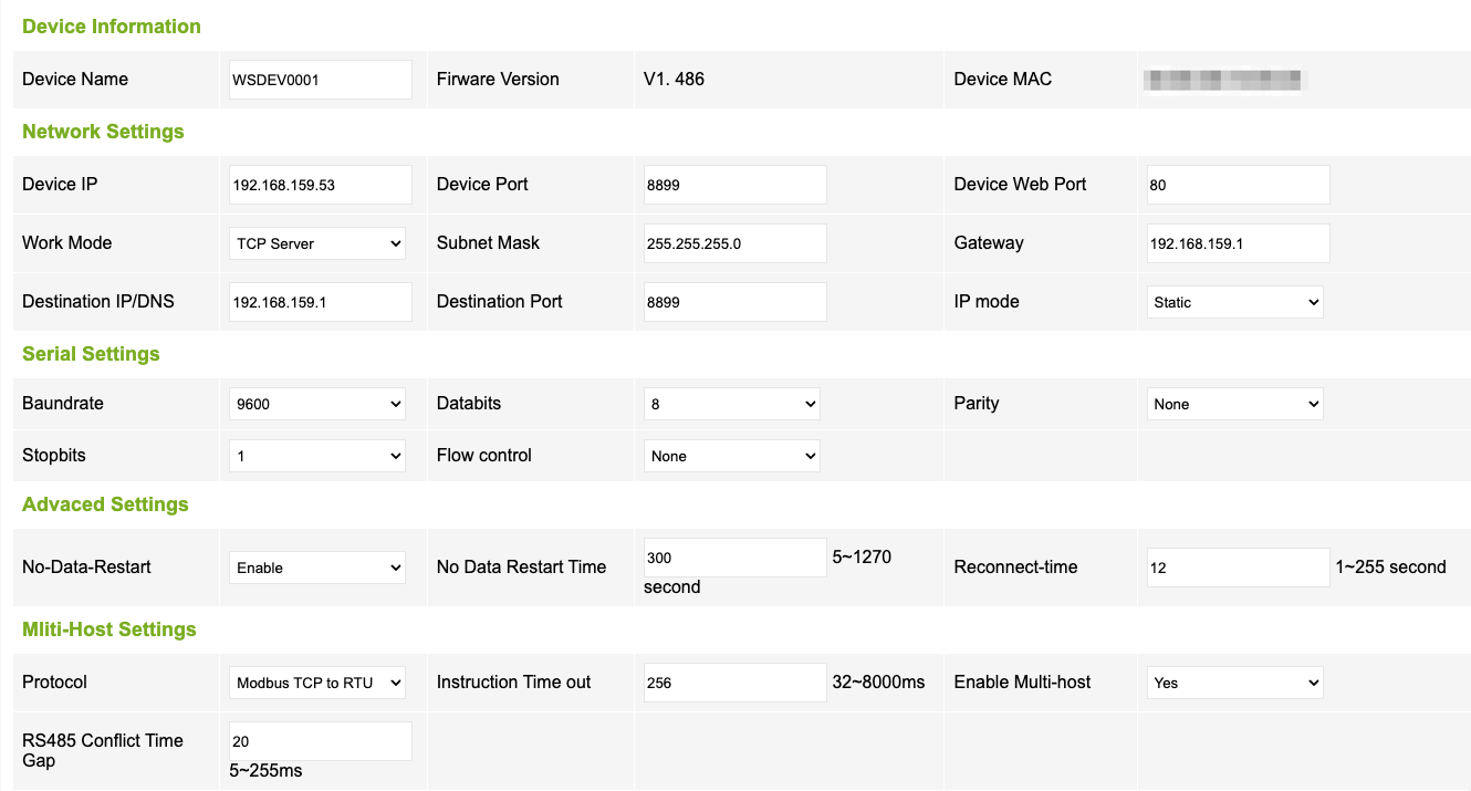
USR-W630 Configuration (Wi-Fi)
Connect the USR-W630 to your home network using the STA Interface Settings.
Set Working Mode Configuration to
Modbus TCP<=>Modbus RTU: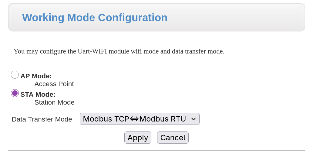
Ensure "Modbus Polling" is disabled:

The add-on connects to
tcp://<server>:<port>The server address of the USR-W630 was obtained through DHCP. You can allocate a fixed IP on your router's DHCP settings.
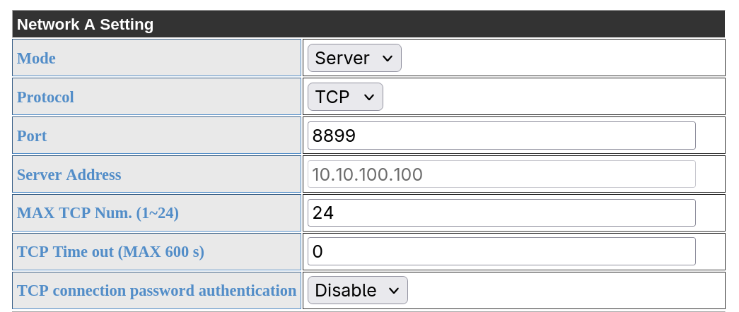
This port is used in the addon configuration when adding the inverter connection.
The server address of the USR-W630 is determined when the network connection was established, the greyed out value here is irrelevant.
USR-W610 Wifi-to-RS485
This is a tested Wifi-to-RS485 gateway. Usually significantly cheaper than the W630, however it does not include a GND.
Requires
READ_SENSORS_BATCH_SIZEset to 8 or lessHF5142B Modbus/serial to ethernet (4x RS232/485/422 to 4x E-Ports)
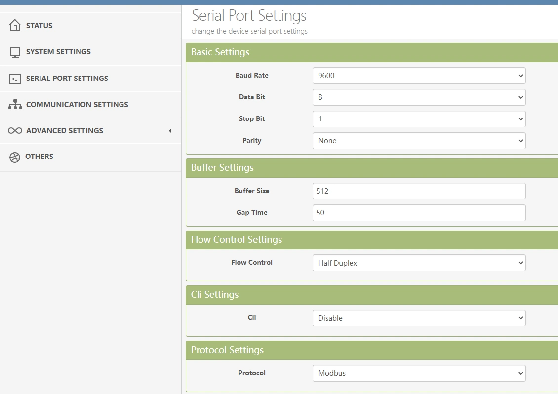
This gateway was tested with the Deye 8k EU Hybrid inverter. The following serial settings were used:
Waveshare RS485 TO (POE) ETH (1x RS485 to 1x E-Port)
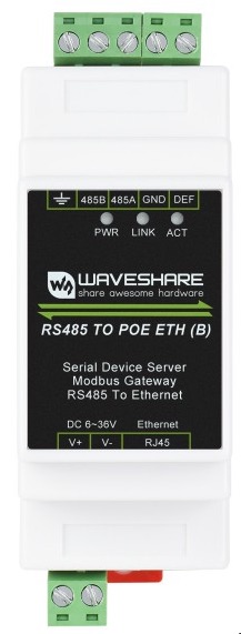
This gateway was tested with the Deye 3 Phase Hybrid Inverter SUN-25K-SG01HP3-EU-AM2. The following serial settings were used:
Sunsynk Inverters
Sunsynk 3.6kW Inverter
Sunsynk Ecco 3.6kW Hybrid Inverter
Model number: SUN-3.6K-SG04LP1-EU
This likely applies to similar models in the Ecco range: SUN-3K-SG04LP1-24-EU / SUN-3K-SG04LP1-EU / SUN-5K-SG04LP1-EU / SUN-6K-SG04LP1-EU
Closer view of the RS485/CAN port
Sunsynk 5.5kW Inverter
Tested with: USB-to-RS485 adaptor sourced from Banggood, very similar to this.
NOTE: RJ-45 port marked RS485 (bottom right) does not work.
Sunsynk 8.8kW Inverter
Tested with: USB-to-485 adaptor sourced from Micro Robotics
Deye Inverters
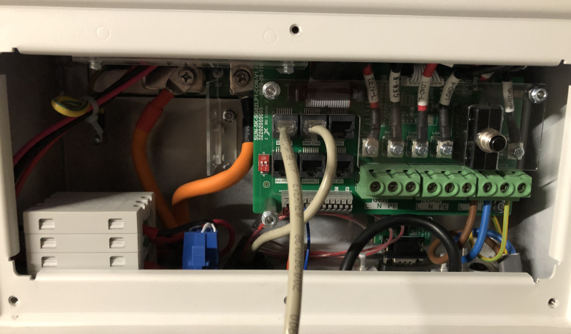
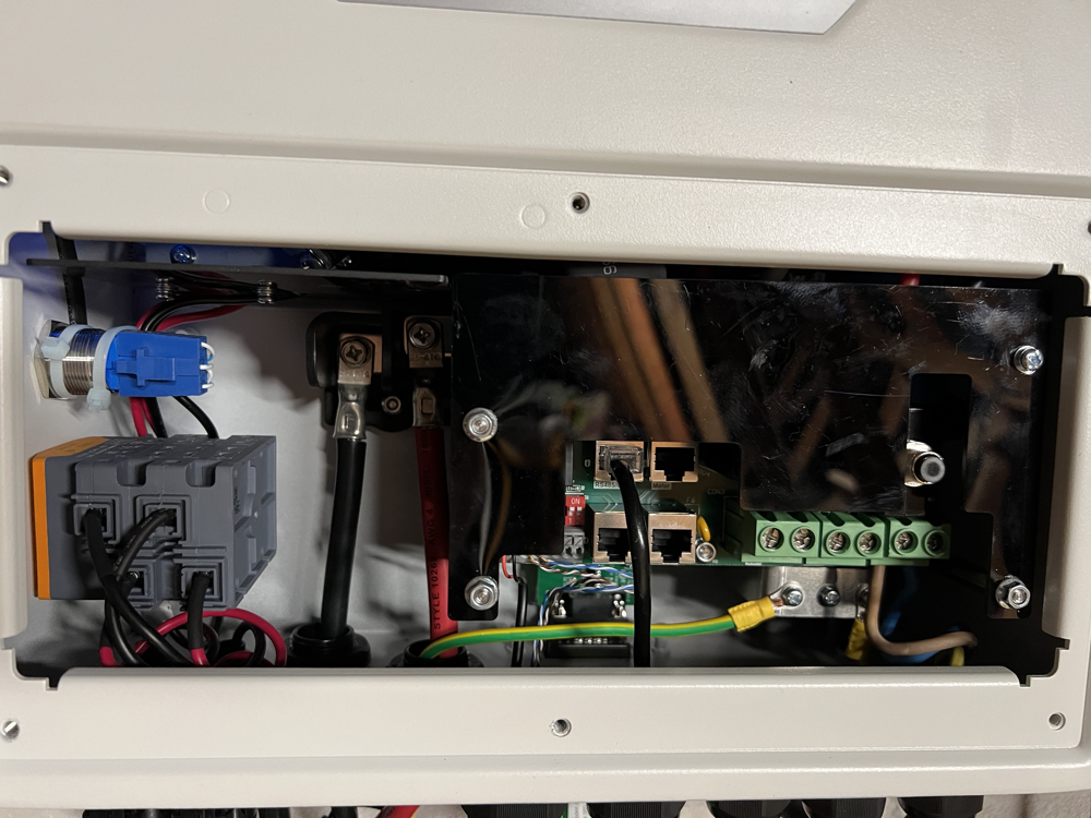
Deye 8kW Inverter
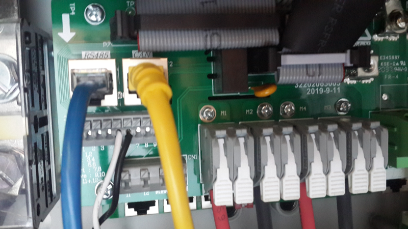
RS485 is the blue line - top left, as with the Sunsynk inverters. Yellow is the CAN-comms with the Pylontech batteries
Deye 25kW HV Inverter
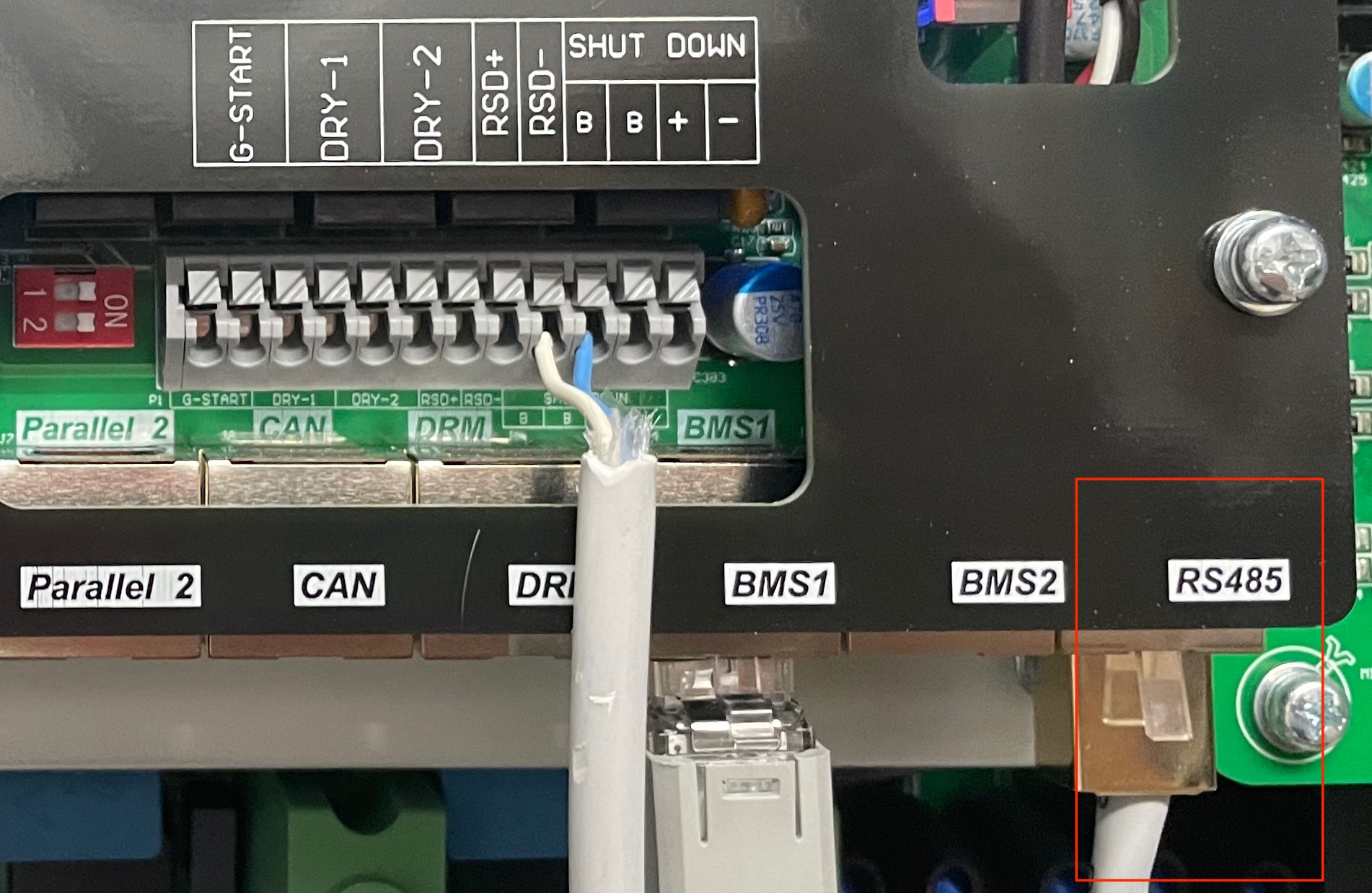
RS485 is the grey line - bottom right. BMS1 is the CAN-comms with the Dyness batteries
Turbo-Energy Inverter
Turbo-Energy 5kW Inverter
Tested with: USB-to-RS485 adaptor sourced from Aliexpress, very similar to this.